What Is a Scissor Lift Mechanism? Types, Components, and Applications
Published
Category
Small Scissor Lift
Learn how a scissor lift mechanism works, explore hydraulic, electric, screw, and manual types, understand key components, and choose the right lifting system.
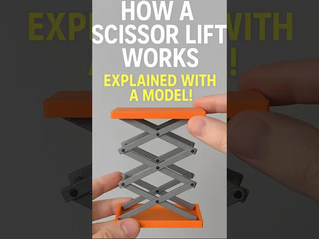
A scissor lift mechanism is a vertical lifting system that uses linked pairs of crossing arms to raise and lower a platform. As the arms rotate around their pivot points, the horizontal linkage movement is converted into controlled vertical motion.
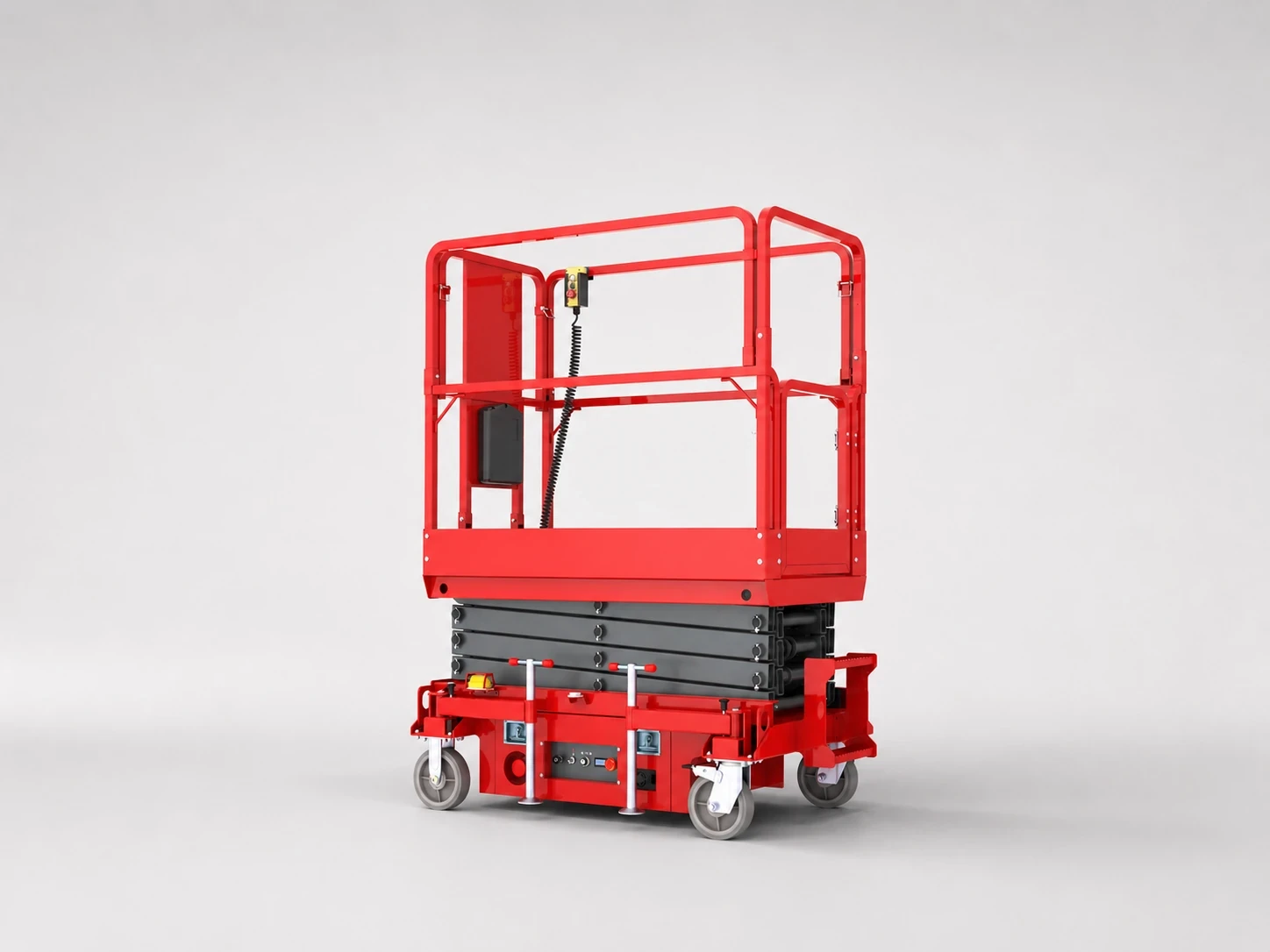
The mechanism is used in many types of equipment, including mobile elevating work platforms (MEWPs), industrial lifting platforms, scissor lift tables, personnel lifts, and material-handling equipment.
The basic linkage is relatively simple, but designing an effective system requires more than connecting two arms with a pivot pin. Lift height, lowered height, rated load, actuator force, arm geometry, stability, platform dimensions, and load distribution all affect how the mechanism performs.
This guide explains how a scissor lift mechanism works, the major components involved, the main mechanism types, engineering considerations, common applications, and the factors buyers should evaluate when selecting lifting equipment.
What Is a Scissor Lift Mechanism?
A scissor lift mechanism is a mechanical linkage system designed to produce vertical platform movement from the rotation or extension of connected lifting arms.
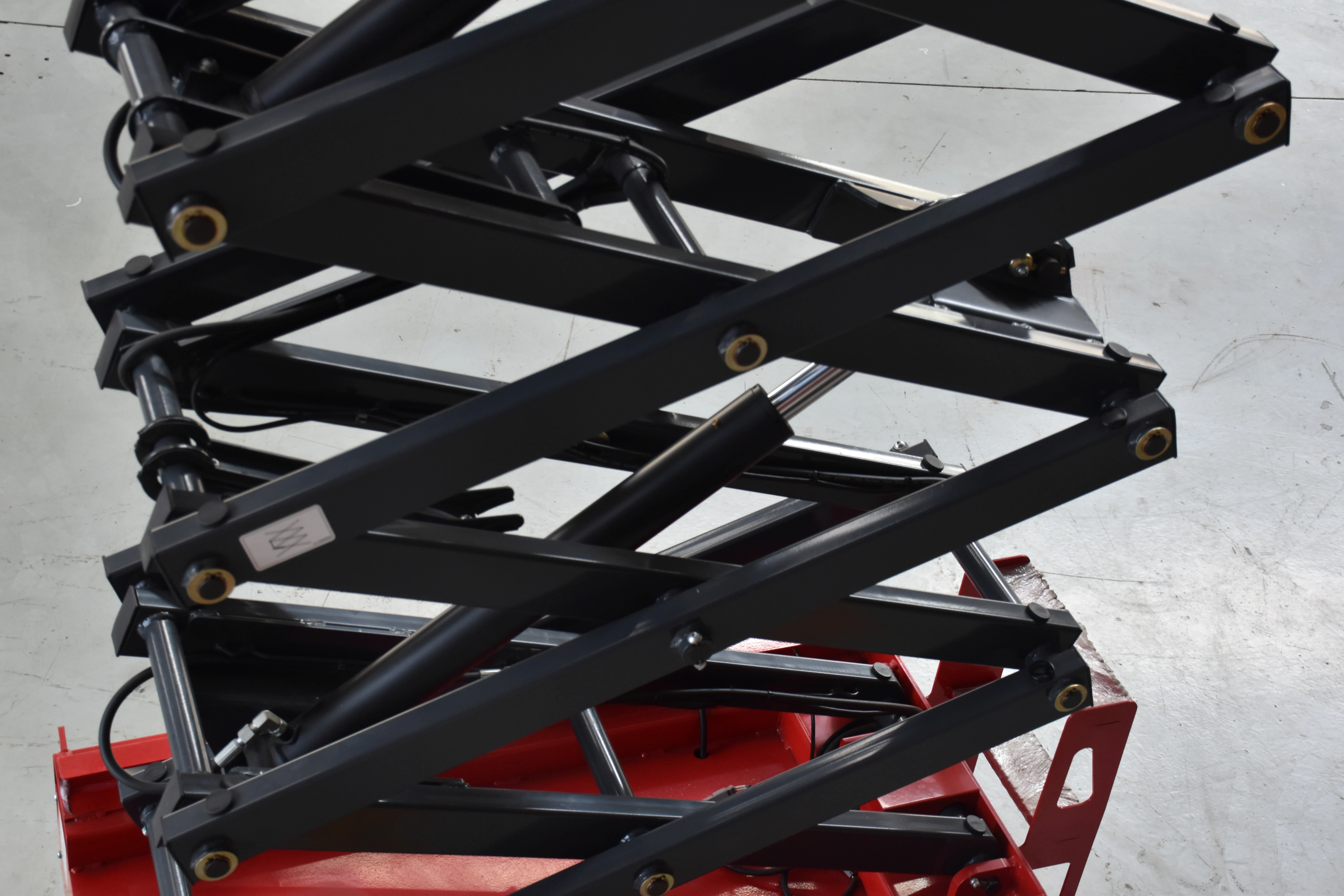
The most recognizable configuration consists of two or more pairs of arms arranged in an “X” or scissors-like pattern. One end of an arm may be fixed or guided, while the other end moves along a roller or guide. An actuator then changes the geometry of the linkage.
When the scissor arms rotate toward a more vertical position, the platform rises. When they spread toward a flatter position, the platform descends.
Why Is It Called a Scissor Mechanism?
The name comes from the appearance of the crossing lifting arms. When viewed from the side, the arms resemble the blades of a pair of scissors opening and closing.
The important engineering principle is not the visual shape itself, but the linkage geometry. The mechanism converts actuator movement into vertical displacement while keeping the platform substantially within the same vertical path.
How Does a Scissor Lift Mechanism Work?
At a simplified level, the operating sequence is:
An actuator applies force to one part of the linkage.
The lifting arms rotate around their pivot points.
Rollers or guided joints allow controlled horizontal movement.
The crossing arms change angle.
The platform moves vertically as the linkage expands or contracts.
The amount of lifting force required changes significantly throughout the stroke. A mechanism that requires relatively high actuator force near its lowest position may require substantially less force as the arms become more vertical.
That is one of the most important characteristics to consider during scissor lift mechanism design.
How Does a Scissor Lift Mechanism Work?
The operation of a scissor lift depends on the interaction between its linkage geometry, actuator, platform, and base.
The Role of the Scissor Arms
The lifting arms form the primary structural linkage. Each arm carries part of the applied load and transfers forces through the pivot joints.
The arms must be designed to withstand:
Vertical compression and tension forces
Bending loads
Repeated loading cycles
Local stress around pin holes
Dynamic loads caused by starting, stopping, and movement
Uneven or offset platform loads
The arm geometry also influences the available lifting height and the amount of actuator movement needed.
The Role of Pivot Points and Rollers
Pivot pins allow the lifting arms to rotate relative to one another. At the same time, rollers or guided ends accommodate the horizontal movement created as the scissor linkage changes angle.
These components may appear secondary, but they have a major influence on mechanism efficiency and durability.
Poor alignment can increase friction, accelerate wear, and create uneven loading. Excessive clearance may contribute to unwanted platform movement, while insufficient clearance can restrict movement as the mechanism loads.
The Role of the Actuator
The actuator supplies the force needed to change the geometry of the linkage.
Depending on the application, the lifting mechanism may use:
Hydraulic cylinders
Electric linear actuators
Lead screws
Ball screws
Mechanical screw drives
Manual actuators
The actuator does not simply “push the platform upward.” It applies force at a particular location on the scissor linkage, and the resulting lifting capacity depends on the mechanical advantage of the linkage at that position.
Scissor Lift Mechanism Components
A complete scissor lifting system contains several interacting subsystems. The exact configuration depends on whether the equipment is designed for personnel access, industrial lifting, warehouse operations, or material handling.
Component | Main Function | Important Design Considerations |
|---|---|---|
Scissor arms | Support and raise the platform | Strength, stiffness, geometry, fatigue |
Pivot pins | Connect moving arms | Shear load, bearing load, wear |
Rollers/guides | Permit controlled horizontal movement | Alignment, friction, load distribution |
Base frame | Supports the linkage | Rigidity, stability, mounting |
Platform | Carries people or material | Rated load, dimensions, deflection |
Hydraulic cylinder | Provides hydraulic lifting force | Stroke, pressure, mounting position |
Electric actuator | Converts motor power to linear motion | Force, stroke, duty cycle |
Lead screw/screw drive | Produces controlled linear motion | Torque, efficiency, wear |
Control system | Commands lifting and lowering | Operator interface, limits, emergency functions |
Safety systems | Reduce operational risk | Application-specific protection and monitoring |
Scissor Arms and Structural Members
The arms are usually among the most highly loaded structural components. Their cross-sectional design affects stiffness, weight, buckling resistance, and fatigue performance.
A heavier arm is not automatically a better arm. Excess structural weight can increase the force required to lift the linkage and reduce the efficiency of the overall system.
Good engineering therefore seeks an appropriate balance between strength, stiffness, mass, manufacturing cost, and service life.
Hydraulic Cylinder or Electric Actuator
The choice of actuator largely determines the character of the lift.
A hydraulic scissor lift mechanism is well suited to applications requiring significant lifting force and robust industrial operation. A hydraulic power unit supplies pressurized fluid to the cylinder.
An electric scissor lift mechanism may use an electric motor with a linear actuator or screw-based transmission. Electric systems can be attractive where controlled motion, lower hydraulic complexity, or battery operation is important.
Platform and Base Frame
The base must transfer the lifting and operating forces into the supporting surface.
The platform, meanwhile, has to support the intended rated load while limiting excessive deflection. Platform dimensions also affect the center of gravity and the distribution of load across the lifting structure.
A platform that is physically large enough for a particular application may still be unsuitable if the load is consistently concentrated at one edge.
Types of Scissor Lift Mechanism
Not all scissor lifts use the same power transmission system. The main difference is how the lifting force is generated and applied.

Hydraulic Scissor Lift Mechanism
Hydraulic systems use a cylinder connected to a hydraulic power unit.
They are widely used because hydraulic cylinders can provide high linear force within a relatively compact package. The system can also be designed for smooth and controlled lifting.
Typical components include a hydraulic pump, reservoir, valves, cylinder, hydraulic lines, and control equipment.
The main engineering considerations include:
Required cylinder force
Cylinder stroke
Hydraulic pressure
Mounting geometry
Duty cycle
Heat generation
Maintenance requirements

Electric Scissor Lift Mechanism
An electric system normally uses an electric motor together with a linear actuator, screw mechanism, or related transmission.
Electric lifting can be useful for equipment that requires accurate movement, battery operation, or integration with electronic control systems.
However, the motor and transmission must be selected based on both the required force and the duty cycle. A motor capable of producing sufficient peak torque may still be unsuitable for continuous or repetitive operation.
Screw and Lead Screw Mechanisms
A screw scissor lift mechanism uses rotational motion to generate controlled linear movement.
Lead screws, Acme screws, or other screw drives can provide precise positioning and mechanical advantage. They can be particularly useful for lifting tables, positioning equipment, and controlled industrial applications.
Designers should evaluate:
Screw load rating
Required travel
Rotation speed
Torque
Efficiency
Lubrication
Wear
Back-driving characteristics
Manual Scissor Lift Mechanisms
Manual systems use operator-applied mechanical force rather than an integrated powered actuator.
They are generally better suited to lighter loads, lower lifting frequency, or situations where simplicity is more important than automation.
Single-Stage and Multi-Stage Configurations
A single-stage scissor linkage provides a practical balance between structural simplicity and lifting height.
When greater vertical travel is required, multiple scissor stages can be connected vertically. A double scissor lift mechanism, for example, can achieve significantly greater height than a single stage without requiring an extremely long individual arm.
The tradeoff is increased structural complexity, more joints, more moving interfaces, and more demanding force analysis.
Scissor Lift Mechanism Design: What Engineers Need to Calculate
The most common mistake in basic lifting-system design is treating the rated load as the only important variable.
A proper scissor lift mechanism design starts with the complete operating envelope.
1. Define Load Capacity
Determine the required rated load first.
This should account for the intended combination of personnel, tools, materials, and equipment. The designer must also consider whether the load is centered or distributed unevenly.
2. Define Minimum and Maximum Height
The mechanism should be evaluated at both its lowered height and maximum lifting height.
The lowest configuration often creates the most demanding actuator-force condition because the scissor arms are at a shallow angle.
3. Establish Platform Geometry
Platform length and width directly influence the center of gravity and structural loading.
The designer should determine how far the center of the working load can move from the centerline and what that offset does to the lifting structure.
4. Determine Actuator Position
Actuator location is critical.
Moving the attachment point changes the moment arm and therefore the force required from the hydraulic cylinder, electric actuator, or screw drive.
An actuator may have adequate nominal force but still fail to produce sufficient lifting performance if the linkage geometry creates a poor mechanical advantage at a critical position.
5. Check Structural Loads
The analysis should include the arms, pins, rollers, frame, and platform.
Important checks include:
Tensile and compressive stresses
Bending stress
Buckling
Pin shear
Bearing stress
Welded-joint strength
Frame deflection
Fatigue under repeated cycles
A Simple Engineering Example
Consider a scissor lifting system that must raise a platform carrying a specified working load.
The first step is not to select a cylinder from the load alone. Instead, the designer needs to examine where the cylinder is attached, the angle of the scissor arms, and the position of the platform throughout the stroke.
Suppose the same platform load is evaluated at two different arm angles. The required actuator force can be dramatically different because the effective mechanical advantage changes with geometry.
This is why scissor lift mechanism calculations should evaluate multiple positions rather than only the fully raised condition.
Scissor Lift Kinematics
Kinematics describes the relationship between the movement of the actuator and the resulting movement of the platform.
A simplified geometric relationship can be represented by:
H ≈ n × L × sin(θ)
where:
H = approximate lifting height
n = number of scissor stages
L = effective arm length
θ = arm angle
This simplified relationship is useful for understanding the basic geometry, but actual equipment requires a more detailed analysis of joints, offsets, roller paths, actuator attachment points, and structural dimensions.
Applications of Scissor Lift Mechanisms
The mechanism is versatile because it provides vertical movement without requiring a large telescoping mast.
Common applications include:
Mobile Elevating Work Platforms
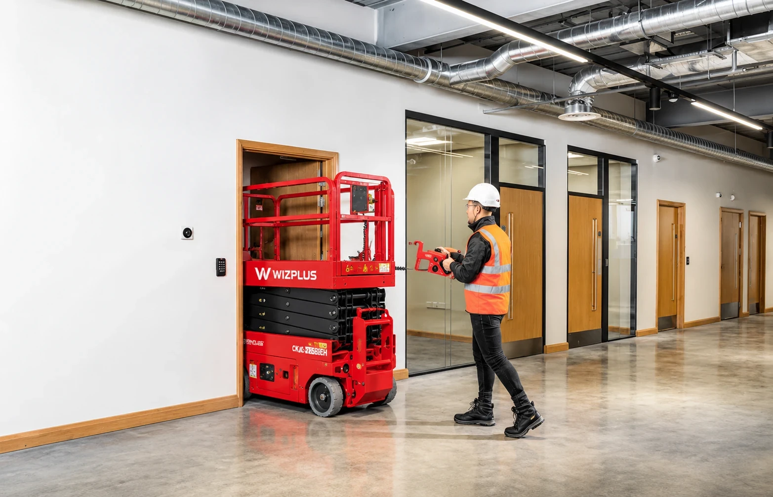
Scissor lifts are widely associated with elevated work access. Workers can be raised vertically to perform installation, maintenance, inspection, electrical work, and other tasks.
In these systems, platform stability, control systems, rated load, and application-specific compliance are critical considerations.
Industrial Scissor Lift Tables
A scissor lift table can raise machinery, components, pallets, or workpieces to a more suitable operating height.
Typical applications include:
Assembly operations
Material handling
Packaging
Production lines
Machine feeding
Ergonomic workstation adjustment
Warehouse and Logistics Equipment
Scissor mechanisms can be integrated into warehouse handling equipment where controlled vertical adjustment is required.
The objective may be to position material at a defined working height rather than to provide personnel access.
Manufacturing and Production Systems
Manufacturers may use lifting platforms to position dies, components, fixtures, and machinery during production or maintenance.
The major advantage is the ability to produce substantial vertical travel from a compact folded configuration.
Advantages and Limitations of a Scissor Lift Mechanism
A scissor linkage offers several practical advantages, but it is not the best solution for every lifting application.
Key Advantages
Compact vertical design: The mechanism can provide significant lifting height from a relatively low starting position.
Direct vertical movement: The platform is primarily designed to move vertically rather than along an arc.
Flexible drive options: Hydraulic, electric, screw, and manual systems are possible.
Scalable configuration: Single-stage and multi-stage arrangements can accommodate different height requirements.
Good platform support: Multiple structural members can distribute the load through the frame.
Wide application range: The mechanism can be used for access equipment, industrial lifts, and material handling.
Common Limitations
Actuator force can become very high at low arm angles.
Multiple pivot joints introduce wear points.
Larger lifting heights can increase structural complexity.
Offset loads can significantly affect stability and structural loading.
The mechanism requires careful synchronization and alignment.
Multi-stage systems demand more detailed engineering and maintenance.
The correct design is therefore not simply the smallest or strongest mechanism. It is the system that provides the required lifting performance across the complete operating range.
How to Choose the Right Scissor Lift Mechanism
For equipment buyers, OEMs, and engineering teams, selecting the right mechanism should begin with application requirements rather than with the actuator type.
Use this evaluation sequence:
Define the application.
Determine whether the lift is intended for personnel, materials, machinery, assembly, maintenance, or another purpose.Set the rated load.
Specify the working load and understand whether it is centered, distributed, or offset.Specify lifting height.
Define both the minimum platform height and the required maximum height.Define platform dimensions.
Consider usable area, center of gravity, access requirements, and allowable platform deflection.Select the drive technology.
Compare hydraulic, electric, screw, or manual systems according to force, speed, duty cycle, precision, and maintenance.Evaluate the complete linkage geometry.
Do not assess actuator capacity only from the nominal platform load.Review operating environment.
Consider indoor or outdoor use, temperature, contamination, moisture, frequency of operation, and available power.Confirm applicable requirements.
For personnel lifting and MEWP applications, review the relevant regulatory and industry requirements for the target market.Specify customization requirements.
OEM projects may require changes to platform dimensions, lifting height, controls, drive systems, branding, or other mechanical interfaces.
This process helps avoid a common purchasing mistake: choosing a lifting capacity that looks correct on paper but does not match the actual operating geometry.
Common Scissor Lift Mechanism Design Mistakes
Several errors repeatedly appear in preliminary designs and equipment specifications.
Designing Only for Maximum Height
The fully raised position is visually important, but the lowest part of the stroke may be more demanding from an actuator-force perspective.
The complete stroke must therefore be analyzed.
Ignoring Off-Center Loading
A platform rated for a particular load does not necessarily behave the same way when that load is concentrated near an edge.
The center of gravity should be considered as part of the original design rather than treated as an afterthought.
Undersizing Pins and Joints
The lifting arms may be strong enough while the pivot interface becomes the weak point.
Pin diameter, shear loading, bearing stress, lubrication, alignment, and wear must all be considered.
Choosing the Actuator Too Early
Selecting a cylinder or actuator before finalizing the linkage geometry can result in poor mechanical advantage or insufficient travel.
The actuator and mechanism should be designed as an integrated system.
Overlooking Duty Cycle
A lifting system used a few times per hour has different requirements from one operating continuously on a production line.
Motor sizing, hydraulic heating, screw wear, and component fatigue are all influenced by duty cycle.
Frequently Asked Questions
How does a scissor lift mechanism work?
A scissor lift mechanism uses interconnected crossing arms. An actuator changes the angle of those arms, causing the linkage to expand or contract vertically and move the platform up or down.
What is a scissor lift mechanism called?
It is commonly described as a scissor mechanism, scissor linkage, scissor lift mechanism, or vertical lifting linkage. The exact terminology depends on the equipment and engineering context.
Are scissor lifts hydraulic?
Some are hydraulic, but not all. Scissor lifts may use hydraulic cylinders, electric linear actuators, lead screws, other mechanical drives, or manual systems.
Are scissor lifts electric?
Many modern lifting systems can use electric drive technology. An electric scissor lift mechanism may combine an electric motor with a linear actuator or screw-based transmission.
Can a scissor lift mechanism be customized?
Yes. For OEM and industrial applications, the mechanism can be engineered around requirements such as lifting height, rated load, platform dimensions, actuator type, operating environment, and control configuration.
What is the difference between a hydraulic and electric scissor lift mechanism?
A hydraulic system generates linear lifting force through pressurized hydraulic fluid and a cylinder. An electric system typically uses a motor-driven actuator or screw mechanism. The better choice depends on required force, speed, duty cycle, precision, available power, and maintenance requirements.
Why do scissor lifts use rollers?
Rollers allow selected ends of the scissor arms to move horizontally as the linkage changes angle. This movement is necessary for the geometry of the mechanism and helps prevent the structure from binding during extension and retraction.
Why is the actuator force higher when the scissor lift is near the bottom?
When the arms are close to horizontal, the linkage generally has poorer mechanical advantage for vertical lifting. As a result, the actuator may need to generate substantially more force to initiate lifting.
Does a higher scissor lift always need more powerful actuators?
Not necessarily. Required actuator force depends on the complete geometry, including arm length, arm angle, actuator location, platform load, and number of stages. A taller mechanism may also use multiple stages or a different linkage arrangement.
Conclusion
A scissor lift mechanism combines a relatively simple crossing-arm linkage with carefully engineered structural and drive components to produce controlled vertical lifting.
Its performance depends on far more than rated capacity. Scissor arm geometry, actuator position, lifting height, lowered height, platform dimensions, pivot design, load distribution, stability, and duty cycle all influence the final system.
Hydraulic, electric, screw, and manual mechanisms each have different strengths. Hydraulic systems can deliver high lifting force, electric systems can support controlled and automated operation, screw mechanisms can provide precise movement, and manual systems can offer simplicity for suitable low-duty applications.
For OEMs, equipment manufacturers, and industrial buyers, the most important lesson is to evaluate the complete lifting system rather than selecting components independently. The actuator, linkage, frame, platform, controls, and operating environment must work together.
WIZPLUSLIFT can support projects that require a purpose-built vertical lifting solution. When discussing an OEM or custom scissor lift project, provide the required load capacity, lifting height, platform dimensions, working environment, drive type, operating frequency, and control requirements so the mechanism can be matched to the application from the beginning.