Scissor Lift Arm Design: Geometry, Loads & Stability
Published
Category
Small Scissor Lift
Learn how scissor lift arm design affects lifting force, load distribution, structural strength, stability, and equipment performance.
Scissor lifts are widely used in construction, warehousing, manufacturing, and industrial maintenance to raise workers, tools, and materials to elevated work areas. Their compact lifting mechanism allows a platform to move vertically while maintaining a relatively simple structural arrangement.
At the center of this system is the scissor arm assembly. The design of these crossed structural members affects how loads are transferred, how the platform rises, and how the lifting mechanism performs throughout its operating range.
Understanding scissor lift arm design is important for equipment manufacturers, engineers, maintenance professionals, and buyers comparing lifting equipment for industrial applications. Arm geometry, material properties, pivot connections, and actuator placement all influence the performance of the complete assembly.
This guide explains how scissor lift arms work, how their geometry affects lifting force, which structural factors engineers must evaluate, and what buyers should consider when selecting a scissor lift.

What Is a Scissor Lift Arm?
A scissor lift arm is a structural member within a lifting mechanism that uses intersecting links to raise and lower a platform. The arms typically form an X-shaped arrangement, with a pivot joint connecting the intersecting members.
As the arms rotate, the distance between the lower and upper sections changes. This movement allows the platform to rise or descend without relying on a conventional vertical mast.
A scissor lift may use a single stage or multiple stages of crossed arms, depending on its required lifting height and overall design.
The main functions of scissor lift arms include:
Supporting the platform through the lifting structure.
Transferring forces between the platform, linkage, and chassis.
Converting actuator movement into vertical platform displacement.
Maintaining the intended geometry of the lifting mechanism.
Working with pivot joints, rollers, and guides throughout the lifting cycle.
Scissor arms do not determine lifting performance independently. Their dimensions, connections, and movement must be evaluated as part of the complete machine.

How Do Crossed Arms Work in a Scissor Lift?
The operating principle of a scissor lift is based on the rotation of connected structural links.
In a typical powered scissor lift, an actuator applies force at designated points on the linkage. As the actuator moves, the arms rotate around their pivots, changing the angle between the arms and the horizontal plane.
This movement increases or decreases the vertical separation between the chassis and platform.
Load transfer through the structure
When workers, tools, or materials are placed on the platform, the resulting forces are transferred through the platform frame to the upper connections of the scissor mechanism. The arms then transmit forces through their members and joints toward the lower connections and chassis.
The actual load distribution depends on the mechanism's geometry, connection locations, number of stages, platform loading, and actuator arrangement.
The role of pivot joints
Pivot joints allow the arms to rotate relative to one another. Additional joints connect the arms to the platform, chassis, or sliding guides.
These connections must accommodate repeated movement while transmitting the forces generated during operation. Joint alignment, pin dimensions, bearing surfaces, and wear resistance are therefore important parts of the overall design.
The role of the actuator
Hydraulic cylinders are commonly used in powered scissor lifts. Depending on the design, the cylinder extends or retracts to move the linkage through its operating range.
The location and orientation of the cylinder affect how its force acts on the arms. Consequently, two scissor lift mechanisms with similar arm dimensions may have different force requirements if their actuator arrangements differ.
How Scissor Lift Arm Geometry Affects Lifting Performance
Arm geometry determines the relationship between the mechanism's physical dimensions and the platform's vertical movement.
Two particularly important variables are arm length and operating angle.
Arm length and lifting height
For an idealized single-stage scissor mechanism, the vertical separation contributed by the crossed arms can be approximated by:
h = L × sin(θ)
Where:
h is the vertical separation between the relevant lower and upper pivot levels.
L is the effective arm length measured between the corresponding end pivots.
θ is the angle of the arm relative to the horizontal.
This relationship assumes a simplified geometry without additional structural offsets. Actual platform height also depends on frame dimensions, pivot arrangements, and the number of stages.
Longer arms can change the available lifting range, but they may also affect the folded dimensions and structural forces. Engineers must consider these trade-offs when determining the appropriate geometry.
Arm angle and lifting force
The arm angle changes as the platform moves between the lowered and raised positions. This affects the mechanical advantage of the linkage and the forces acting on the arms and actuator.
Near the fully lowered position, a scissor mechanism may require greater actuator force to initiate lifting because of its geometric configuration. The precise force requirement depends on the actuator attachment points, linkage arrangement, friction, and applied load.
This is why scissor lift arm design should be evaluated at multiple positions throughout the lifting cycle rather than at only one operating height.
Single-stage and multi-stage arrangements
A single-stage mechanism uses one level of crossed arms. Multi-stage arrangements combine multiple scissor assemblies to achieve greater vertical extension within a particular equipment configuration.
Adding stages changes the total height, number of connections, overall geometry, and load distribution. The design must therefore account for the behavior of the entire assembly rather than treating each stage as an isolated component.
Key Factors in Scissor Lift Arm Design
A reliable scissor lift structure requires coordinated consideration of geometry, strength, stiffness, connections, and the operating environment.
Material Selection and Structural Strength
Scissor lift arms are commonly manufactured from structural metals such as steel. The appropriate material depends on the equipment's load requirements, dimensions, manufacturing process, fatigue demands, and design specifications.
Material selection is not simply a question of choosing the strongest available steel. The structural member must perform adequately under the loads and operating conditions for which the equipment is designed.
Engineers should consider several potential failure modes.
Yielding: Permanent deformation can occur when stresses exceed the applicable material limit.
Buckling: A structural member under compression may become unstable before the material reaches its nominal strength.
Fatigue: Repeated loading and unloading can cause fatigue damage over time, particularly around stress concentrations and connections.
Excessive deflection: Structural deformation can affect the intended alignment and operation of the lifting mechanism.
These failure modes require different forms of evaluation. Selecting a material with high tensile strength alone does not demonstrate that an arm assembly is safe or suitable for its intended load.
Cross-Section and Structural Stiffness
The cross-sectional shape and dimensions of a scissor arm influence its stiffness, resistance to bending, and resistance to buckling.
A design must account for how the member is loaded and supported. The direction of the applied forces and the effective length between restraints can influence structural behavior.
Designers also need to evaluate local stresses around holes, cutouts, welded joints, and other areas where the geometry changes.
Increasing the amount of material may improve some structural properties, but it can also increase the weight of the moving assembly. Additional weight can influence the forces required to lift the structure and may affect other equipment design requirements.
The objective is to establish a suitable balance between structural performance, equipment weight, manufacturability, and service life.
Pivot Location and Connection Design
The locations of the arm pivots determine how the mechanism moves and how forces travel through its structure.
Small changes in pivot placement can alter the relationship between actuator movement and platform displacement. They can also change the mechanical advantage and the reactions at individual connections.
Important considerations include pin dimensions, bearing pressure, connection alignment, clearances, and the strength of the surrounding structural material.
These components should be designed as part of the complete linkage. Evaluating the arm members without checking the connections may overlook important sources of stress or wear.
Manufacturing Quality
Manufacturing processes influence the accuracy and consistency of the finished arm assembly.
Dimensional control is important because the arms must align with their pivot points and any associated rollers or sliding guides. Incorrect hole positions or inconsistent component dimensions may affect assembly and movement.
Where welding is used, the design and manufacturing process should account for joint requirements, material compatibility, and quality inspection.
Inspection and verification procedures should correspond to the equipment's actual design and applicable requirements.
How Pivot Pins, Bushings, and Rollers Affect Performance
Scissor lift arms rely on several supporting components to move correctly under load. These components are sometimes smaller than the main structural members, but their condition can directly affect the linkage.
Pivot pins and bushings
Pivot pins connect moving structural members, while bushings may provide bearing surfaces between the pins and surrounding components.
Their design must account for the forces at the joint, the required rotational movement, and expected operating cycles.
Common inspection concerns include excessive clearance, visible wear, damaged retainers, and abnormal movement. Lubrication requirements vary by component and should follow the manufacturer's instructions.
Rollers and sliding guides
Some scissor lift mechanisms use rollers or sliding guides to accommodate changes in the distance between selected connection points as the platform rises.
The guide arrangement influences the movement of the arms and the way forces are transferred to the supporting frame.
Damaged rollers, worn guide surfaces, or alignment problems may lead to restricted or uneven movement. The exact inspection and replacement procedures depend on the mechanism's design.
Why component condition matters
A lifting structure is a connected mechanical system. Wear at one joint can affect alignment elsewhere in the linkage, while damage to a guide may interfere with the intended movement of the arms.
For this reason, maintenance should cover the complete assembly, not just the visible steel members.
How Scissor Lift Arm Design Affects Load Capacity
Scissor lift load capacity refers to the permitted load under the equipment manufacturer's specified conditions. It cannot be determined from arm thickness or material strength alone.
The complete system must be considered, including:
Structural arms and their cross-sections.
Pivot pins, bushings, and connection details.
Platform and chassis strength.
Actuator force and attachment geometry.
Number of lifting stages and operating position.
Load distribution across the platform.
Applicable operating limitations and safety requirements.
The effect of load distribution
A centered load and an unevenly distributed load can produce different reactions in the lifting mechanism.
The location of the load affects the forces transferred through individual members and connections. Engineers therefore need to evaluate the loading conditions specified for the equipment rather than assuming that all platform positions create identical forces.
The effect of lifting height
The geometry of the arms changes as the platform rises. This can change the forces acting on structural members, pivots, and the actuator.
The design should be assessed across the relevant operating range, including positions where the mechanism experiences demanding force conditions.
Why rated capacity must be verified
Equipment buyers should rely on the manufacturer's rated capacity and operating instructions rather than attempting to estimate the load rating visually.
The rated capacity must not be exceeded, and load placement must remain within the limits specified for the model. The same principle applies to tools, materials, and personnel carried on the platform.
Common Scissor Lift Arm Problems and Inspection Points
Routine inspection helps identify changes in the condition of the lifting structure. It should be performed according to the manufacturer's instructions and applicable requirements.
Worn pivot connections
Worn pins or bushings may develop excessive clearance. Abnormal looseness, visible damage, or unexpected movement should be assessed by qualified service personnel.
Bent or cracked structural arms
Structural deformation or cracking may indicate damage caused by impact, overloading, fatigue, or another abnormal condition.
Equipment with suspected structural damage should be removed from service until it has been evaluated. Structural members should not be straightened, welded, or modified without an appropriate approved repair procedure.
Damaged rollers or guides
Worn or damaged guide components may interfere with smooth movement. Inspection should identify visible damage, unusual wear, and signs that components are no longer tracking correctly.
Corrosion and surface deterioration
Corrosion can compromise the condition of load-bearing sections or connection areas. The severity depends on its location, extent, and effect on the remaining material.
Abnormal movement or noise
Unusual noise, jerky movement, or unexpected changes during lifting may indicate a mechanical, hydraulic, or control-system problem. These symptoms should be investigated rather than ignored.
Inspection findings should be documented and defects addressed before the equipment returns to operation when they may affect safe use.
How to Choose a Scissor Lift Based on Its Structural Design
For equipment buyers, understanding scissor lift arm design helps when comparing machines for a particular application. However, structural design is only one part of a complete purchasing decision.
Working height and platform dimensions
Confirm the required working height, platform dimensions, and available clearance. Distinguish working height from platform height when comparing specifications.
Rated load capacity
Check the published capacity and any restrictions on load distribution or platform extensions. Do not assume that models with similar dimensions have equivalent ratings.
Indoor or outdoor operation
Consider the working surface, ground conditions, space restrictions, and environmental conditions. A suitable configuration depends on the actual worksite and the equipment's specified operating capabilities.
Lifting mechanism and folded dimensions
Review the number of scissor stages, the overall dimensions when lowered, and the equipment's maximum working height. The objective is to select a configuration that meets the task requirements without creating unnecessary space or operating constraints.
Maintenance and technical support
Ask the manufacturer or supplier about inspection procedures, replacement parts, technical documentation, and service support. Access to model-specific information helps maintenance teams manage the equipment throughout its service life.
When comparing scissor lift manufacturers, request technical documentation for the exact model and verify that its specifications match your application.
Frequently Asked Questions
What is the purpose of scissor lift arms?
Scissor lift arms form the crossed-linkage structure that supports the platform and enables vertical movement. They transfer forces through the lifting mechanism to the chassis while working with pivot connections, guides, and the actuator.
How does scissor arm angle affect lifting force?
The arm angle affects the mechanical advantage of the linkage and the forces required from the actuator. A shallow arm angle can create demanding lifting-force requirements, depending on the mechanism's geometry and actuator attachment points.
What materials are used for scissor lift arms?
Structural metals, including steel, are commonly used. The material grade, cross-sectional dimensions, and manufacturing process depend on the equipment's design requirements and structural verification.
Do longer scissor arms provide greater lifting height?
Arm length influences vertical travel, but actual lifting height also depends on the linkage configuration, pivot locations, number of stages, and folded dimensions. Arm length should therefore be evaluated as part of the complete design.
What causes scissor lift arms to wear?
Wear may develop at pivot pins, bushings, rollers, and guide surfaces because of repeated movement and operating loads. Inadequate maintenance, contamination, misalignment, or abnormal operating conditions may also contribute, depending on the equipment design.
Can a damaged scissor lift arm be repaired?
Only an approved repair procedure should be used for a load-bearing structural member. The manufacturer or an appropriately qualified engineering professional should assess the damage and determine whether repair or replacement is suitable.
Conclusion
Scissor lift arm design is fundamental to the movement, structural performance, and load-handling capability of a lifting platform. Arm geometry determines how the mechanism changes height, while material properties, connection design, actuator placement, and component condition influence its performance under load.
For manufacturers and equipment buyers, evaluating these factors provides a more complete understanding of how a scissor lift is designed and what to look for when comparing equipment.
When selecting a scissor lift for industrial or material-handling applications, consider the rated load capacity, working height, platform dimensions, operating environment, and model-specific technical documentation.
Looking for a scissor lift for your application? Explore WIZPLUS scissor lift solutions and contact the team to discuss your required working height, load capacity, and equipment specifications.
Scissor lifts are widely used in construction, warehousing, manufacturing, and industrial maintenance to raise workers, tools, and materials to elevated work areas. Their compact lifting mechanism allows a platform to move vertically while maintaining a relatively simple structural arrangement.
At the center of this system is the scissor arm assembly. The design of these crossed structural members affects how loads are transferred, how the platform rises, and how the lifting mechanism performs throughout its operating range.
Understanding scissor lift arm design is important for equipment manufacturers, engineers, maintenance professionals, and buyers comparing lifting equipment for industrial applications. Arm geometry, material properties, pivot connections, and actuator placement all influence the performance of the complete assembly.
This guide explains how scissor lift arms work, how their geometry affects lifting force, which structural factors engineers must evaluate, and what buyers should consider when selecting a scissor lift.
What Is a Scissor Lift Arm?
A scissor lift arm is a structural member within a lifting mechanism that uses intersecting links to raise and lower a platform. The arms typically form an X-shaped arrangement, with a pivot joint connecting the intersecting members.
As the arms rotate, the distance between the lower and upper sections changes. This movement allows the platform to rise or descend without relying on a conventional vertical mast.
A scissor lift may use a single stage or multiple stages of crossed arms, depending on its required lifting height and overall design.
The main functions of scissor lift arms include:
Supporting the platform through the lifting structure.
Transferring forces between the platform, linkage, and chassis.
Converting actuator movement into vertical platform displacement.
Maintaining the intended geometry of the lifting mechanism.
Working with pivot joints, rollers, and guides throughout the lifting cycle.
Scissor arms do not determine lifting performance independently. Their dimensions, connections, and movement must be evaluated as part of the complete machine.
How Do Crossed Arms Work in a Scissor Lift?
The operating principle of a scissor lift is based on the rotation of connected structural links.
In a typical powered scissor lift, an actuator applies force at designated points on the linkage. As the actuator moves, the arms rotate around their pivots, changing the angle between the arms and the horizontal plane.
This movement increases or decreases the vertical separation between the chassis and platform.
Load transfer through the structure
When workers, tools, or materials are placed on the platform, the resulting forces are transferred through the platform frame to the upper connections of the scissor mechanism. The arms then transmit forces through their members and joints toward the lower connections and chassis.
The actual load distribution depends on the mechanism's geometry, connection locations, number of stages, platform loading, and actuator arrangement.
The role of pivot joints
Pivot joints allow the arms to rotate relative to one another. Additional joints connect the arms to the platform, chassis, or sliding guides.
These connections must accommodate repeated movement while transmitting the forces generated during operation. Joint alignment, pin dimensions, bearing surfaces, and wear resistance are therefore important parts of the overall design.
The role of the actuator
Hydraulic cylinders are commonly used in powered scissor lifts. Depending on the design, the cylinder extends or retracts to move the linkage through its operating range.
The location and orientation of the cylinder affect how its force acts on the arms. Consequently, two scissor lift mechanisms with similar arm dimensions may have different force requirements if their actuator arrangements differ.
How Scissor Lift Arm Geometry Affects Lifting Performance
Arm geometry determines the relationship between the mechanism's physical dimensions and the platform's vertical movement.
Two particularly important variables are arm length and operating angle.
Arm length and lifting height
For an idealized single-stage scissor mechanism, the vertical separation contributed by the crossed arms can be approximated by:
h = L × sin(θ)
Where:
h is the vertical separation between the relevant lower and upper pivot levels.
L is the effective arm length measured between the corresponding end pivots.
θ is the angle of the arm relative to the horizontal.
This relationship assumes a simplified geometry without additional structural offsets. Actual platform height also depends on frame dimensions, pivot arrangements, and the number of stages.
Longer arms can change the available lifting range, but they may also affect the folded dimensions and structural forces. Engineers must consider these trade-offs when determining the appropriate geometry.
Arm angle and lifting force
The arm angle changes as the platform moves between the lowered and raised positions. This affects the mechanical advantage of the linkage and the forces acting on the arms and actuator.
Near the fully lowered position, a scissor mechanism may require greater actuator force to initiate lifting because of its geometric configuration. The precise force requirement depends on the actuator attachment points, linkage arrangement, friction, and applied load.
This is why scissor lift arm design should be evaluated at multiple positions throughout the lifting cycle rather than at only one operating height.
Single-stage and multi-stage arrangements
A single-stage mechanism uses one level of crossed arms. Multi-stage arrangements combine multiple scissor assemblies to achieve greater vertical extension within a particular equipment configuration.
Adding stages changes the total height, number of connections, overall geometry, and load distribution. The design must therefore account for the behavior of the entire assembly rather than treating each stage as an isolated component.
Key Factors in Scissor Lift Arm Design
A reliable scissor lift structure requires coordinated consideration of geometry, strength, stiffness, connections, and the operating environment.
Material Selection and Structural Strength
Scissor lift arms are commonly manufactured from structural metals such as steel. The appropriate material depends on the equipment's load requirements, dimensions, manufacturing process, fatigue demands, and design specifications.
Material selection is not simply a question of choosing the strongest available steel. The structural member must perform adequately under the loads and operating conditions for which the equipment is designed.
Engineers should consider several potential failure modes.
Yielding: Permanent deformation can occur when stresses exceed the applicable material limit.
Buckling: A structural member under compression may become unstable before the material reaches its nominal strength.
Fatigue: Repeated loading and unloading can cause fatigue damage over time, particularly around stress concentrations and connections.
Excessive deflection: Structural deformation can affect the intended alignment and operation of the lifting mechanism.
These failure modes require different forms of evaluation. Selecting a material with high tensile strength alone does not demonstrate that an arm assembly is safe or suitable for its intended load.
Cross-Section and Structural Stiffness
The cross-sectional shape and dimensions of a scissor arm influence its stiffness, resistance to bending, and resistance to buckling.
A design must account for how the member is loaded and supported. The direction of the applied forces and the effective length between restraints can influence structural behavior.
Designers also need to evaluate local stresses around holes, cutouts, welded joints, and other areas where the geometry changes.
Increasing the amount of material may improve some structural properties, but it can also increase the weight of the moving assembly. Additional weight can influence the forces required to lift the structure and may affect other equipment design requirements.
The objective is to establish a suitable balance between structural performance, equipment weight, manufacturability, and service life.
Pivot Location and Connection Design
The locations of the arm pivots determine how the mechanism moves and how forces travel through its structure.
Small changes in pivot placement can alter the relationship between actuator movement and platform displacement. They can also change the mechanical advantage and the reactions at individual connections.
Important considerations include pin dimensions, bearing pressure, connection alignment, clearances, and the strength of the surrounding structural material.
These components should be designed as part of the complete linkage. Evaluating the arm members without checking the connections may overlook important sources of stress or wear.
Manufacturing Quality
Manufacturing processes influence the accuracy and consistency of the finished arm assembly.
Dimensional control is important because the arms must align with their pivot points and any associated rollers or sliding guides. Incorrect hole positions or inconsistent component dimensions may affect assembly and movement.
Where welding is used, the design and manufacturing process should account for joint requirements, material compatibility, and quality inspection.
Inspection and verification procedures should correspond to the equipment's actual design and applicable requirements.
How Pivot Pins, Bushings, and Rollers Affect Performance
Scissor lift arms rely on several supporting components to move correctly under load. These components are sometimes smaller than the main structural members, but their condition can directly affect the linkage.
Pivot pins and bushings
Pivot pins connect moving structural members, while bushings may provide bearing surfaces between the pins and surrounding components.
Their design must account for the forces at the joint, the required rotational movement, and expected operating cycles.
Common inspection concerns include excessive clearance, visible wear, damaged retainers, and abnormal movement. Lubrication requirements vary by component and should follow the manufacturer's instructions.
Rollers and sliding guides
Some scissor lift mechanisms use rollers or sliding guides to accommodate changes in the distance between selected connection points as the platform rises.
The guide arrangement influences the movement of the arms and the way forces are transferred to the supporting frame.
Damaged rollers, worn guide surfaces, or alignment problems may lead to restricted or uneven movement. The exact inspection and replacement procedures depend on the mechanism's design.
Why component condition matters
A lifting structure is a connected mechanical system. Wear at one joint can affect alignment elsewhere in the linkage, while damage to a guide may interfere with the intended movement of the arms.
For this reason, maintenance should cover the complete assembly, not just the visible steel members.
How Scissor Lift Arm Design Affects Load Capacity
Scissor lift load capacity refers to the permitted load under the equipment manufacturer's specified conditions. It cannot be determined from arm thickness or material strength alone.
The complete system must be considered, including:
Structural arms and their cross-sections.
Pivot pins, bushings, and connection details.
Platform and chassis strength.
Actuator force and attachment geometry.
Number of lifting stages and operating position.
Load distribution across the platform.
Applicable operating limitations and safety requirements.
The effect of load distribution
A centered load and an unevenly distributed load can produce different reactions in the lifting mechanism.
The location of the load affects the forces transferred through individual members and connections. Engineers therefore need to evaluate the loading conditions specified for the equipment rather than assuming that all platform positions create identical forces.
The effect of lifting height
The geometry of the arms changes as the platform rises. This can change the forces acting on structural members, pivots, and the actuator.
The design should be assessed across the relevant operating range, including positions where the mechanism experiences demanding force conditions.
Why rated capacity must be verified
Equipment buyers should rely on the manufacturer's rated capacity and operating instructions rather than attempting to estimate the load rating visually.
The rated capacity must not be exceeded, and load placement must remain within the limits specified for the model. The same principle applies to tools, materials, and personnel carried on the platform.
Common Scissor Lift Arm Problems and Inspection Points
Routine inspection helps identify changes in the condition of the lifting structure. It should be performed according to the manufacturer's instructions and applicable requirements.
Worn pivot connections
Worn pins or bushings may develop excessive clearance. Abnormal looseness, visible damage, or unexpected movement should be assessed by qualified service personnel.
Bent or cracked structural arms
Structural deformation or cracking may indicate damage caused by impact, overloading, fatigue, or another abnormal condition.
Equipment with suspected structural damage should be removed from service until it has been evaluated. Structural members should not be straightened, welded, or modified without an appropriate approved repair procedure.
Damaged rollers or guides
Worn or damaged guide components may interfere with smooth movement. Inspection should identify visible damage, unusual wear, and signs that components are no longer tracking correctly.
Corrosion and surface deterioration
Corrosion can compromise the condition of load-bearing sections or connection areas. The severity depends on its location, extent, and effect on the remaining material.
Abnormal movement or noise
Unusual noise, jerky movement, or unexpected changes during lifting may indicate a mechanical, hydraulic, or control-system problem. These symptoms should be investigated rather than ignored.
Inspection findings should be documented and defects addressed before the equipment returns to operation when they may affect safe use.
How to Choose a Scissor Lift Based on Its Structural Design
For equipment buyers, understanding scissor lift arm design helps when comparing machines for a particular application. However, structural design is only one part of a complete purchasing decision.
Working height and platform dimensions
Confirm the required working height, platform dimensions, and available clearance. Distinguish working height from platform height when comparing specifications.
Rated load capacity
Check the published capacity and any restrictions on load distribution or platform extensions. Do not assume that models with similar dimensions have equivalent ratings.
Indoor or outdoor operation
Consider the working surface, ground conditions, space restrictions, and environmental conditions. A suitable configuration depends on the actual worksite and the equipment's specified operating capabilities.
Lifting mechanism and folded dimensions
Review the number of scissor stages, the overall dimensions when lowered, and the equipment's maximum working height. The objective is to select a configuration that meets the task requirements without creating unnecessary space or operating constraints.
Maintenance and technical support
Ask the manufacturer or supplier about inspection procedures, replacement parts, technical documentation, and service support. Access to model-specific information helps maintenance teams manage the equipment throughout its service life.
When comparing scissor lift manufacturers, request technical documentation for the exact model and verify that its specifications match your application.
Frequently Asked Questions
What is the purpose of scissor lift arms?
Scissor lift arms form the crossed-linkage structure that supports the platform and enables vertical movement. They transfer forces through the lifting mechanism to the chassis while working with pivot connections, guides, and the actuator.
How does scissor arm angle affect lifting force?
The arm angle affects the mechanical advantage of the linkage and the forces required from the actuator. A shallow arm angle can create demanding lifting-force requirements, depending on the mechanism's geometry and actuator attachment points.
What materials are used for scissor lift arms?
Structural metals, including steel, are commonly used. The material grade, cross-sectional dimensions, and manufacturing process depend on the equipment's design requirements and structural verification.
Do longer scissor arms provide greater lifting height?
Arm length influences vertical travel, but actual lifting height also depends on the linkage configuration, pivot locations, number of stages, and folded dimensions. Arm length should therefore be evaluated as part of the complete design.
What causes scissor lift arms to wear?
Wear may develop at pivot pins, bushings, rollers, and guide surfaces because of repeated movement and operating loads. Inadequate maintenance, contamination, misalignment, or abnormal operating conditions may also contribute, depending on the equipment design.
Can a damaged scissor lift arm be repaired?
Only an approved repair procedure should be used for a load-bearing structural member. The manufacturer or an appropriately qualified engineering professional should assess the damage and determine whether repair or replacement is suitable.
Conclusion
Scissor lift arm design is fundamental to the movement, structural performance, and load-handling capability of a lifting platform. Arm geometry determines how the mechanism changes height, while material properties, connection design, actuator placement, and component condition influence its performance under load.
For manufacturers and equipment buyers, evaluating these factors provides a more complete understanding of how a scissor lift is designed and what to look for when comparing equipment.
When selecting a scissor lift for industrial or material-handling applications, consider the rated load capacity, working height, platform dimensions, operating environment, and model-specific technical documentation.
Looking for a scissor lift for your application? Explore WIZPLUS scissor lift solutions and contact the team to discuss your required working height, load capacity, and equipment specifications.
SELF-PROPELLED ORDER PICKING LIFT
OPC Series
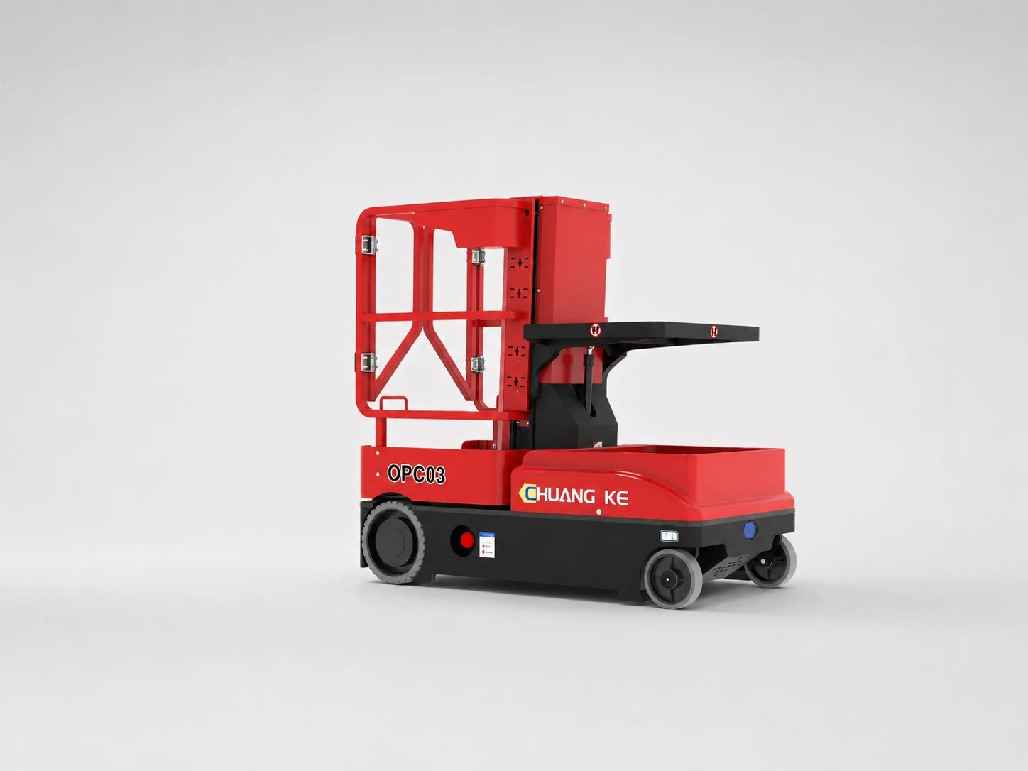
SELF-PROPELLED ORDER PICKING LIFT
OPC Series
SELF-PROPELLED SINGLE-MAST LIFT
AM-S
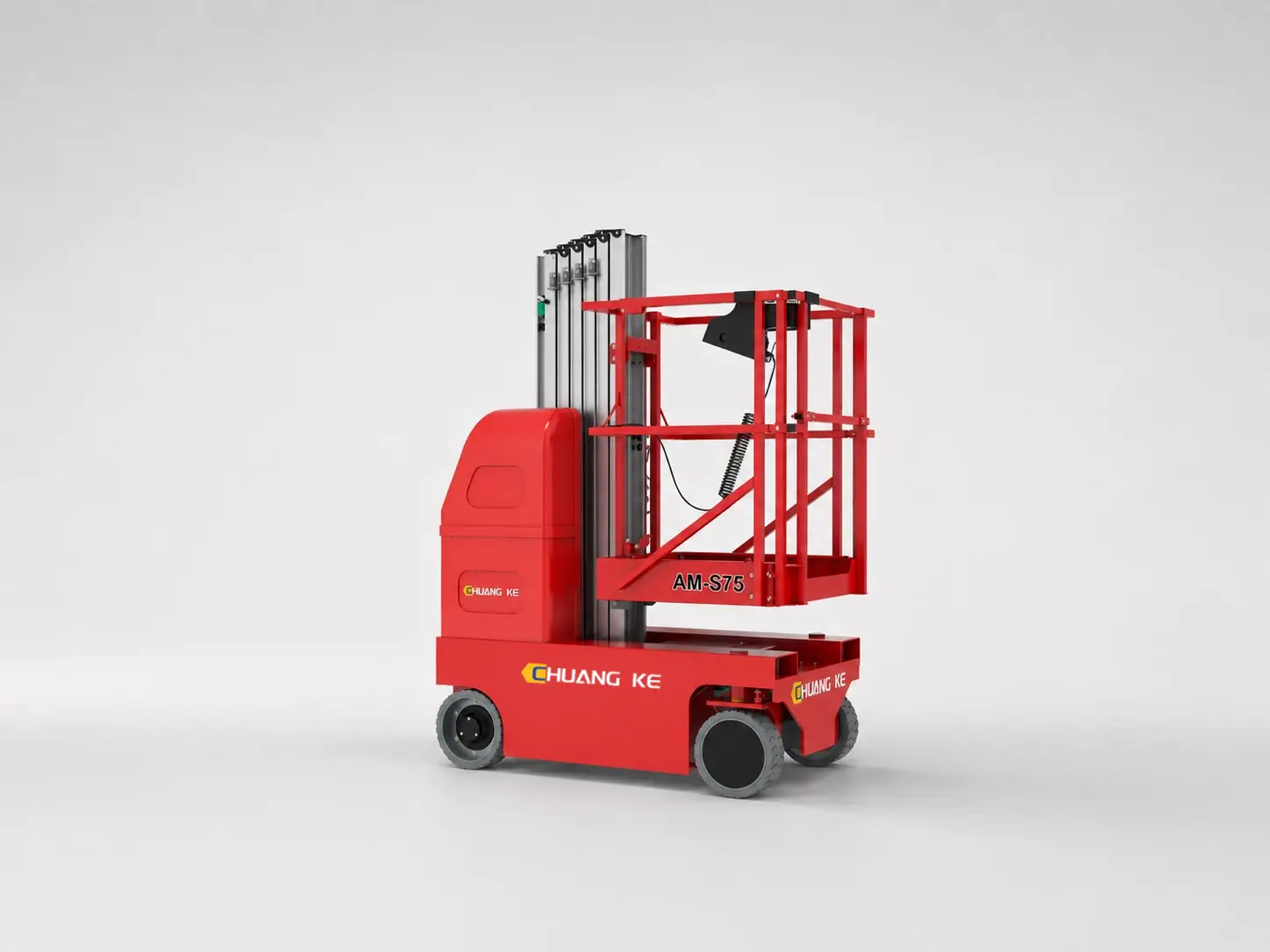
SELF-PROPELLED SINGLE-MAST LIFT
AM-S
SEMI ELECTRIC SCISSOR LIFT
CKJC-Y Series
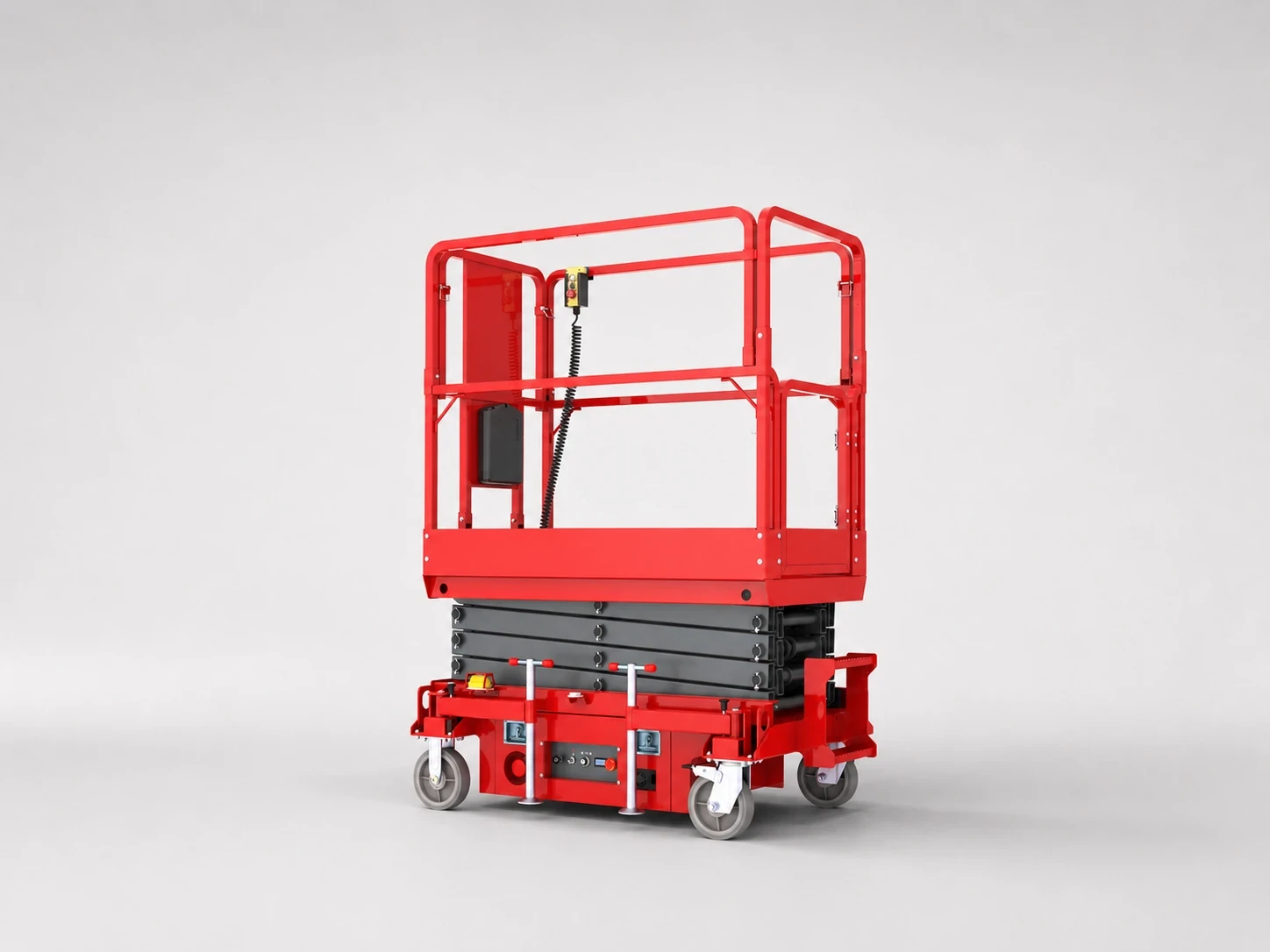
SEMI ELECTRIC SCISSOR LIFT
CKJC-Y Series
Looking for a Trusted Order Picker & Scissor Lift Manufacturer?
WIZPLUS delivers reliable aerial work and material handling solutions with competitive factory pricing, OEM & ODM customization, professional technical support, and responsive service for customers worldwide.


